6 Plug Trailer Wiring Diagram
Trailer Wiring Diagrams Trailer Wiring Connectors Various connectors are available from four to seven pins that allow for the transfer of power for the lighting as well as auxiliary functions such as an electric trailer brake controller, backup lights, or a 12V power supply for a winch or interior trailer lights.
7 Pin Trailer Plug Wiring Diagram Flat Wiring Diagram
Identify the wires: The first step is to identify the wires coming out of your trailer plug. There are typically six wires in a 6 wire trailer plug: ground, brake, tail lights, left turn, right turn, and reverse lights. Use a wire stripper to remove about 1/2 inch of insulation from the ends of each wire. Connect the ground wire: The ground.

6 Pin Trailer Connector Wiring Diagram Free Wiring Diagram
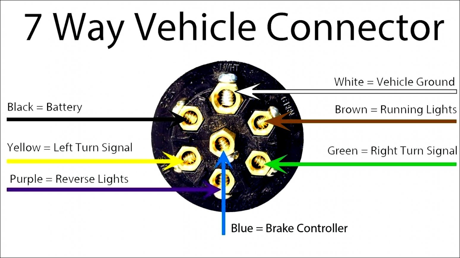
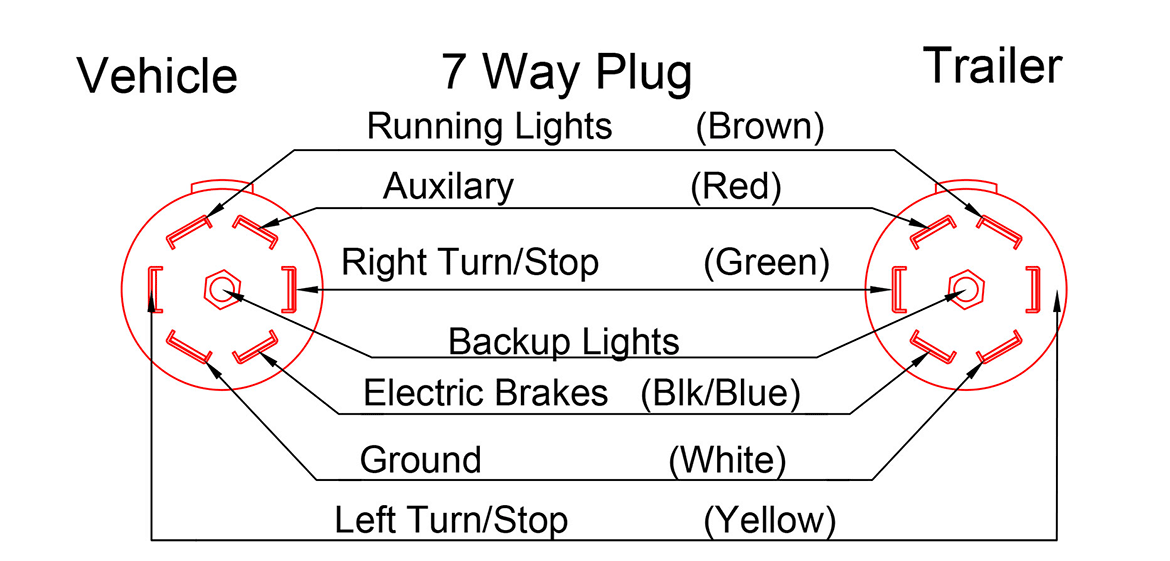
7 Way Plug Wiring Diagram Standard Wiring* This is the most common (Standard) wiring scheme for RV Plugs and the one used by major auto manufacturers today. * Always test wires for function and wire accordingly. This wiring scheme is for reference only. copyright © 2001, Country Trailer Sales All Rights Reserved
Trailer Wiring Diagram 7 Pin Round Wiring Diagram
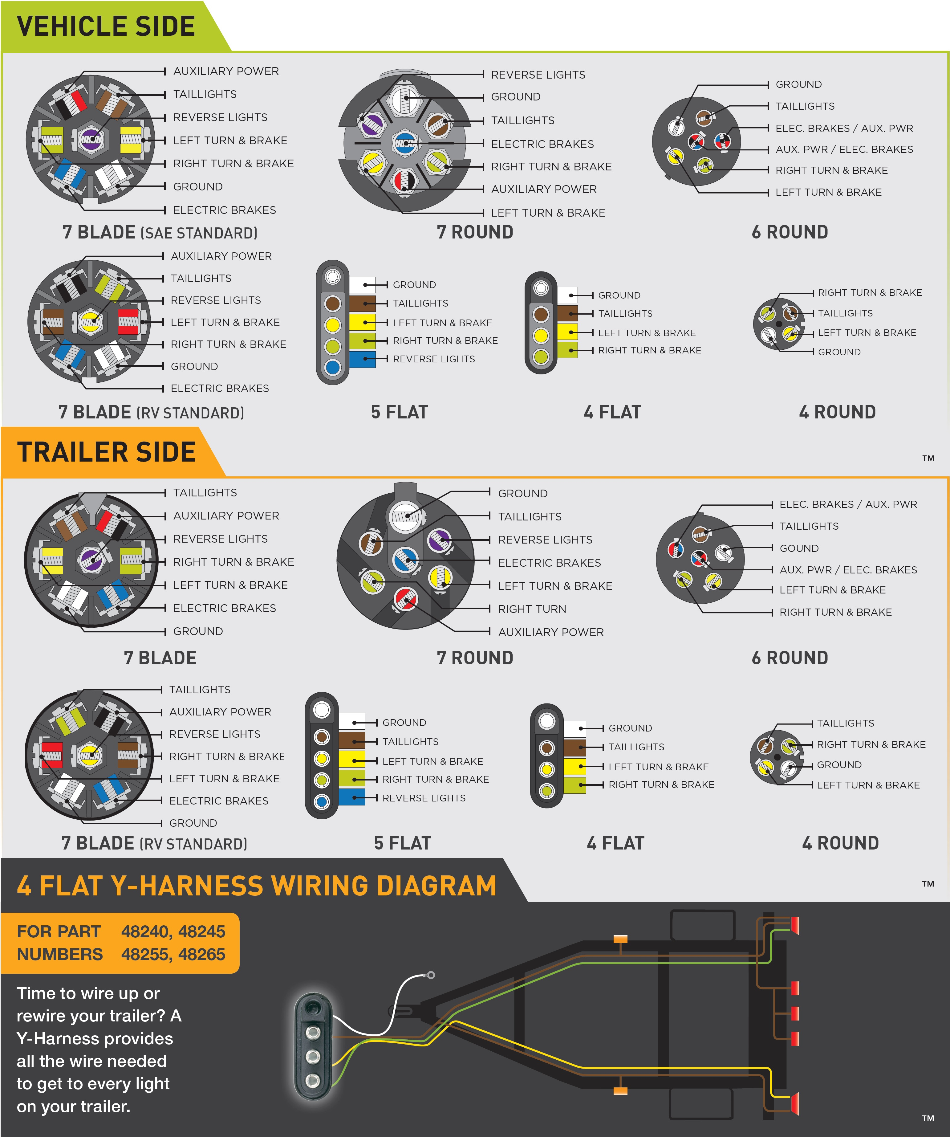
CAR END 4 & 5 Way Flat Connector Wiring Diagrams 4-way and 5-way flat connectors use color-coded wires and are available in a variety of lengths. They can be purchased as a standalone plug for the truck or trailer, or as a complete loop with both the plug and the socket included.
7 Pin Trailer Plug Wiring Diagram Wiring Diagram
Trailer Wiring Connectors Various connectors are available from four to seven pins that allow for the transfer of power for the lighting as well as auxiliary functions such as an electric trailer brake controller, backup lights, or a 12V power supply for a winch or interior trailer lights.

7 point plug trailer wiring diagram
At a minimum, all trailers need at least 4 functions: Tail lights, Brake lights, Left & Right signals. 4 wires will give these functions, so the simplest scheme is a 4-pin connector. The most common 4 wire connector is the 4-Pin Flat Connector as shown here.
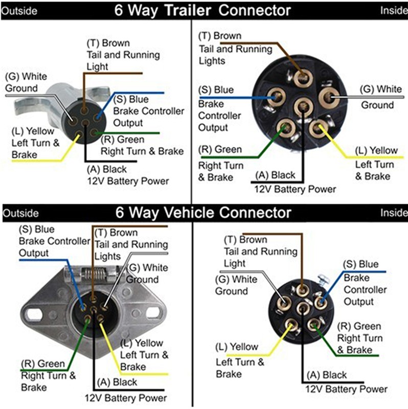
6 Way Trailer Plug Wiring Diagram Wiring Diagram
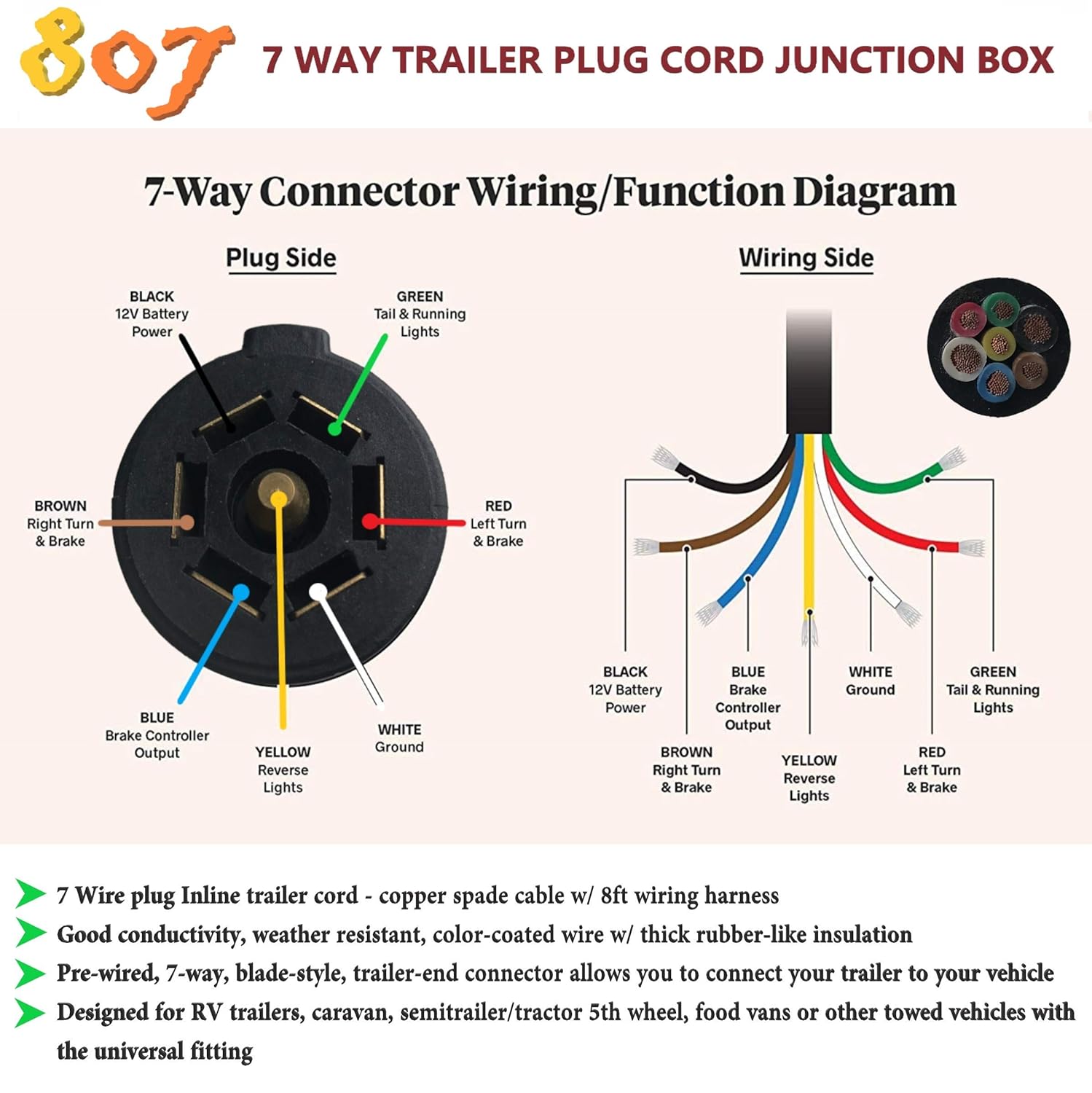
The 7-pin trailer plug is the most common type used for connecting trailers to vehicles, providing all the necessary signals for lights, brakes, and other electrical components. In this comprehensive guide, we will walk you through the complete wiring diagram for a 7-pin trailer plug, making installation a breeze.
Hopkins Trailer Connector Wiring Diagram Wiring Diagram
The 7-Way Trailer Plug is around 2″ diameter connector that allows an additional pin for an auxiliary 12-volt power or backup lights. It is usually used for towing heavy-duty cargo trailers, aluminum trailers, dump trailers, utility / landscape trailers, equipment trailers, open car haulers and enclosed car haulers.
Plug Wiring Diagram Double A Trailers
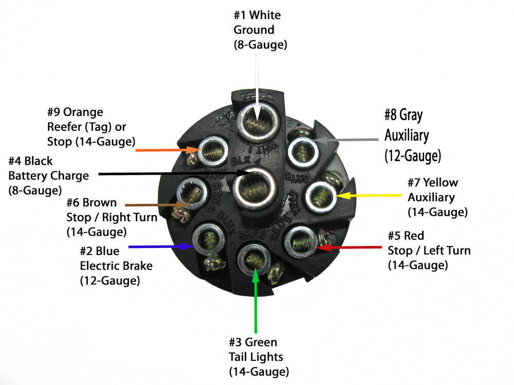
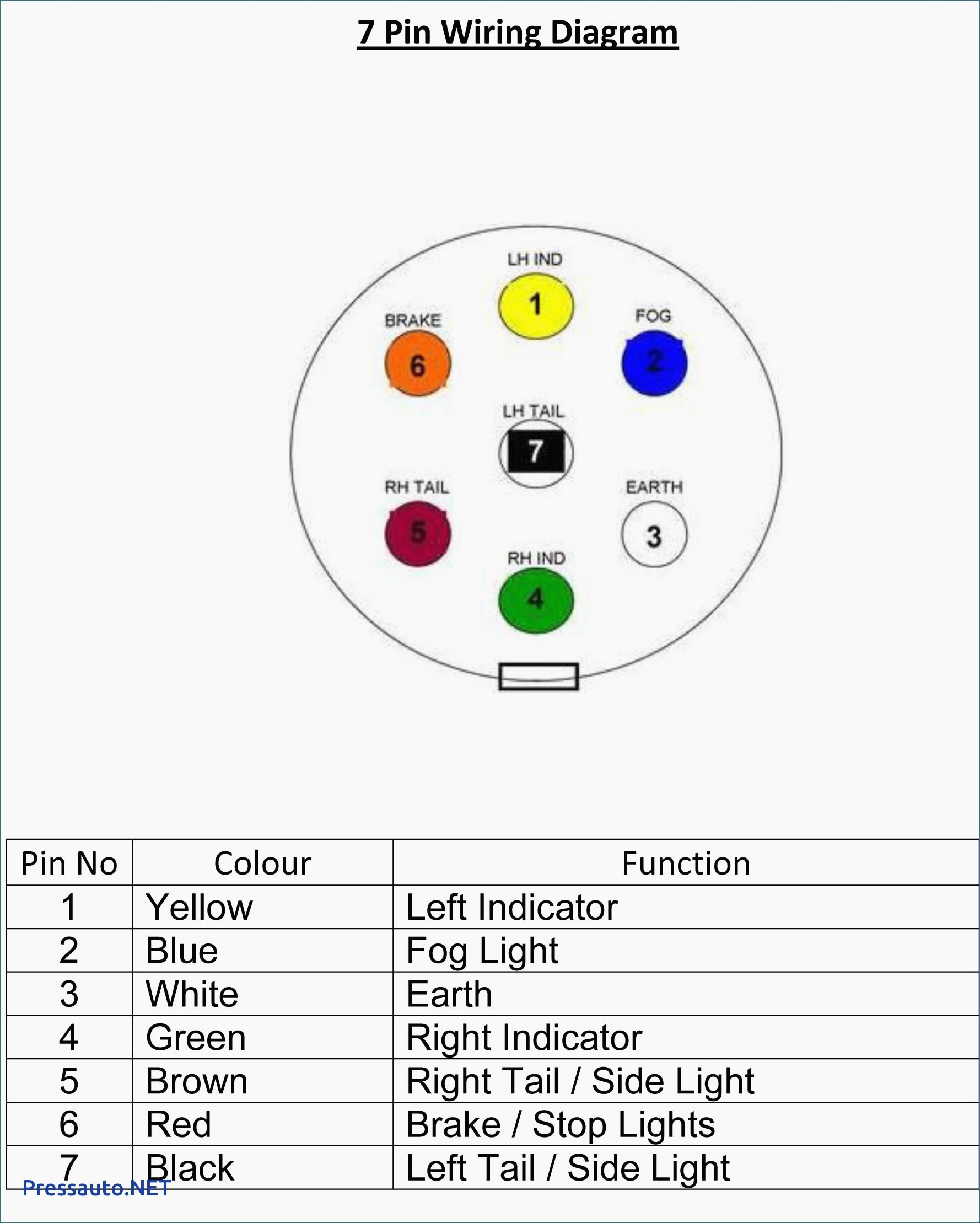
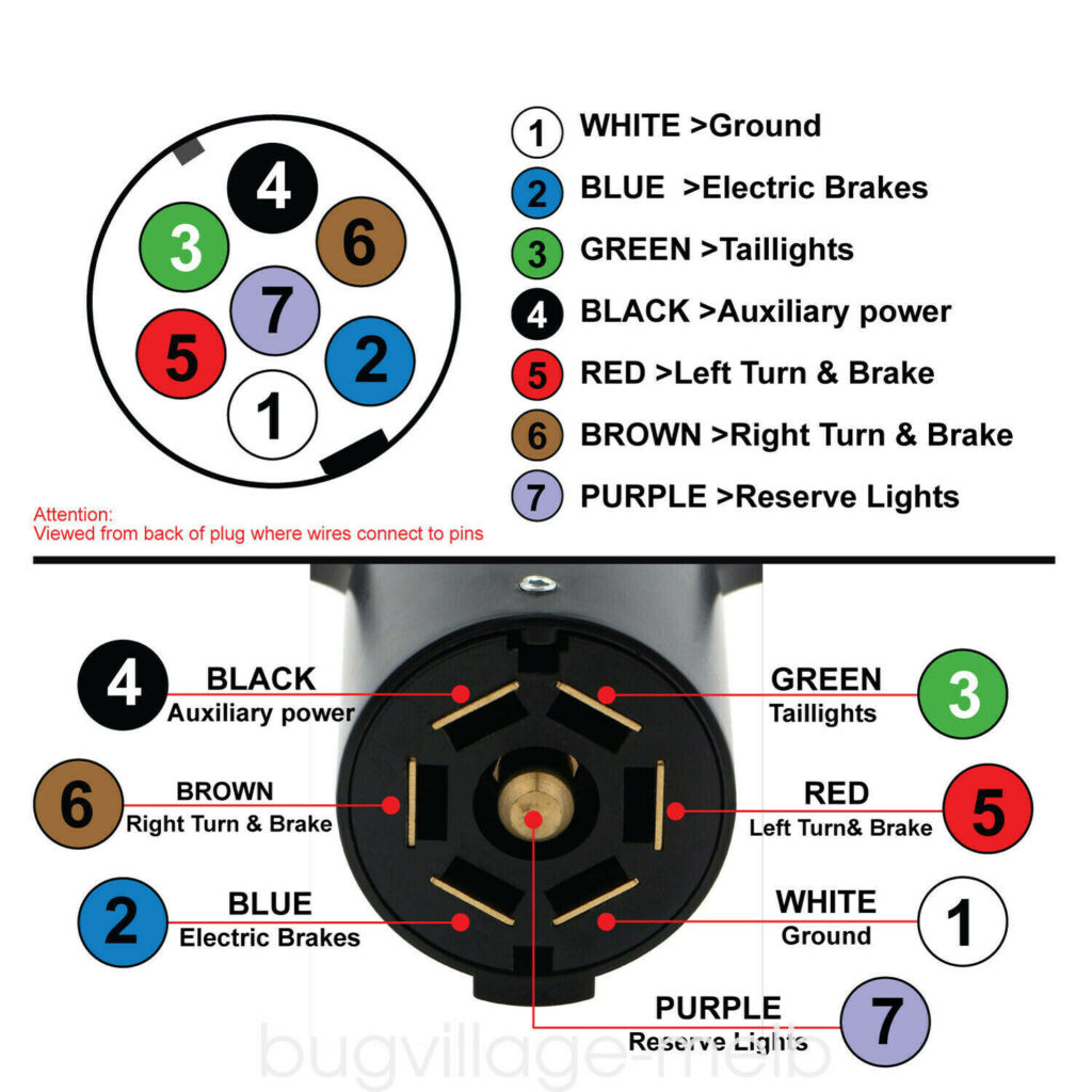
A 7 pin trailer wiring diagram is a schematic that shows the pinout and function of each wire in a 7-way round trailer connector. The standard 7-pin connector contains the following wires and functions: The diagram uses color coding and labeling to identify the purpose of each pin's wire. It traces the path of the wires from the connector.
Wiring For 7 Pin Trailer Plug
A 4-way plug connects your trailer and tow vehicle and provides the required running lights, turn signals, ground, and brake lights. Most of us aren't electricians, but that doesn't mean wiring a trailer or replacing corroded wiring is beyond us. We'll walk you through the wiring process--it's easier than you think!

7 Pin Trailer Plug Wiring Diagram Usa Wiring Harness Diagram
Custom wiring is the ideal solution for installing trailer light wiring on your vehicle. A custom wiring harness or 'T-connector' is a vehicle-specific harness that plugs in without any spicing required and provides a standard connector output, such as a 4-way flat.
4 Pin Trailer Wiring Diagram 4 Pin Trailer Connector Wiring Diagram in 2020 Trailer
This step-by-step guide covers wiring a 7-pin trailer plug to connect your trailer lights. Learn how to gather materials, read wiring diagrams, connect and test wires, secure wiring, and inspect final connections. Follow these steps to wire your trailer plug correctly and troubleshoot lighting issues.

Wiring Diagram For A Trailer Connector
Trailer plug wiring diagrams are essential for understanding how to properly connect the electrical components of a trailer to a vehicle. These diagrams provide a visual representation of the wiring connections, ensuring that the right wires are connected to the right components.
7 Way Trailer Plug Wiring Diagram Ford F250 where to get trailer plug wiring diagram Ford
The 7-way trailer plug wiring diagram is a valuable tool that can help you easily install the wiring for your trailer's electrical connections.. This may include a wiring harness, a 7-way trailer plug, wire crimpers, electrical tape, and a voltage tester. Having everything prepared in advance will make the installation process go smoothly..

Wiring Diagram For 7 Prong Trailer Plug Trailer Wiring Diagram
The main purpose of 7-way connectors is to transfer electricity for powering lights, electric brakes, charging batteries, and various accessories between an RV or tow vehicle and the attached trailer. There are two key components that make up these systems: The 7-pin connectors and wiring mounted on both the vehicle and trailer

Rv Trailer Plug Wiring Diagram Non Commercial Truck, Fifth in 7 Wire Trailer Plug Diagram
If you have a 4-way plug, add a 5-way with a 4-to-5-way adapter Use a circuit tester to confirm wire function. Step 2: Connect Ground to Vehicle Frame Just like we did on the trailer, we now have to connect the ground on the vehicle side. Attach the white ground wire to a clean, bare metal surface on the vehicle frame.